 |
|
 |
|
|
|
Building a dc to ac converter
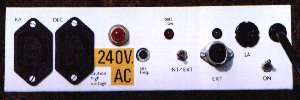
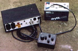
Otherwise known as a dual axis drive corrector, this unit is intended to provide 240 volts/50 Hz (or 120 volts/60 Hz with minor modifications) for a right ascension (ra) drive and a reversible declination motor. Both these outputs are isolated from ground and from the 12 volt supply. This isn't a complex project and uses readily available parts, but if you fancy building this project and don't possess the necessary electronic construction skills, there are likely to be fellow astronomers who can assist. I've built two of these units back in 1987 and they have worked without fault ever since. The supply requirement is from 11 to 16 volts d.c. at 500 mA, a cheap "burglar alarm" sealed lead acid gel cell will provide sufficient capacity for a typical viewing or photography session. A complete Adobe Acrobat version of this article is available to download via this link.
Circuit description
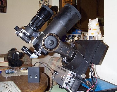
The 12 volt input is fed via a 2 amp fuse and series diode to both T1 and IC5. IC5 is a 5 volt output regulator feeding IC1 to IC4 including the remote controller. IC1(A) (NE555) forms a free running oscillator with a frequency determined by the value of resistance between pins 6 and 7. The oscillator has a nominal frequency of 10 KHz, this relatively high frequency was chosen so that a high stability capacitor could be used at C10 to give minimum drift with changes in temperature. Virtually identical oscillators are fitted to both the main and remote units. R4 and R5 are omitted from the main unit. Switch S1 is fitted to the front panel of the main unit and selects either local or remote oscillators. The remote unit is connected via a latching "DIN" plug and socket or similar connectors. The remote unit is only required for photographic tracking and can be omitted altogether for visual work. IC2 and IC3 are wired to divide by 10, giving 1 KHz and 100 Hz outputs. The 100Hz output of IC3 is fed to the input of a flip flop (IC4) which feed the signal alternately to the bases of TR1 and TR2, these switch the 12 volt supply to ground through transformer T1 which is a normal mains transformer connected in reverse. The switched declination output is taken from the output of T1 via RLA or RLB. Either of these relays being energised when PB3 or PB4 is pressed on the remote unit. A 0.1uF (400 volt working) capacitor gives a phase shift to the declination motor. Note the declination reversing switch mounted on the remote control, this is used to reverse the "sense" of the push buttons to match the view through the eyepiece when tracking (wire a double pole change over slide switch from corner to corner in a cross so that it reverses the connections, not shown on diagram). The overall output frequency is adjustable from 47.5 Hz to 52.5 Hz by adjusting RV1 or from 40 Hz to 60 Hz by pressing PB1 or PB2 on the remote unit. This frequency is stabilised against voltage or temperature change. By changing the value of R2 and R2A the unit can be made to work for a 60 Hz motor rather than 50 Hz. Note that references to IC1 also include IC1A of the remote unit. Modifications and USA part numbers I've received details of circuit changes to improve the output voltage and also USA part numbers from Pete Killingworth (pkillingsworth at cox dotnet). The main change is to reduce the value of R7 and R8 to drive the output transistors with more current. Pete is driving a Bausch & Lomb 4000 and finds the inverter works well.
Diagram with USA part numbers 98KB gif image
Construction It is strongly suggested that you download the PIA program and associated zip files, using these to print a good quality board layout. There is also a layout for the hand held remote controller.
The relay board isn't (yet) available in PIA format, however it's a simple
design and can be produced from this layout diagram
Perhaps the easiest way of producing a printed circuit board is to print the layout at the correct size, stick it to the copper side of a piece of blank copper PC board, drill through the holes, clean the board and draw the layout with an etch resist pen. Finally etch in ferric chloride and wash.

Parts List
Notes All fixed resistors are 1% metal film 1/4 watt The 54K resistor is made up from 51K and 3K resistors, it is selected on test to give the required output frequency. Parts for the oscillator in the hand controller are identical to those used on the main board. While Maplin are mentioned as a supplier of some parts, nothing in this design is critical, there shouldn't be a problem with finding these parts at any of the usual suppliers. The frequency determining components around IC1 should be chosen with care to minimise drift due to changes in temperature, in particular a good quality potentiometer should be chosen for RV1. © 1997, D Johnson. All rights reserved
|
||||||||||||||||||||||||||||||||||||||||

 Please refer to the schematic, it is available both
as a
Please refer to the schematic, it is available both
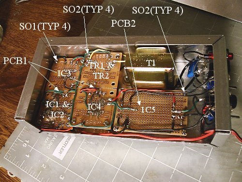
as a 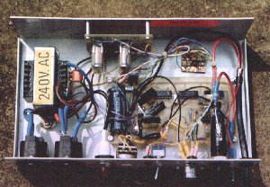 Various component locations are shown on the PIA board layouts, is it generally
accepted practice to fit ic sockets, then resistors, capacitors, transtors
etc. However the exact construction is very much up to the individual and
is beyond the scope of this web page, if you lack the experience to tackle
a project such as this, there are likely to be plenty of electronics enthusiasts
in your local astronomy club who can assist.
Various component locations are shown on the PIA board layouts, is it generally
accepted practice to fit ic sockets, then resistors, capacitors, transtors
etc. However the exact construction is very much up to the individual and
is beyond the scope of this web page, if you lack the experience to tackle
a project such as this, there are likely to be plenty of electronics enthusiasts
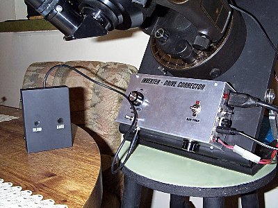
in your local astronomy club who can assist. 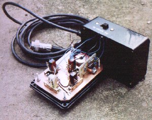 If you take a close look at the image of the remote controller, you will
see that the various parts are mounted on a sub-board made from printed circuit
board, this makes it easy to mount the push button switches without having
to fix them to the front panel. The remote oscillator board is simply soldered
onto this main board.
If you take a close look at the image of the remote controller, you will
see that the various parts are mounted on a sub-board made from printed circuit
board, this makes it easy to mount the push button switches without having
to fix them to the front panel. The remote oscillator board is simply soldered
onto this main board. 